Forefront TMG within Hyper-V Private Clouds


The following describes a high availability architecture for Forefront TMG within Hyper-V for IaaS Private Cloud supporting an web application tier and data storage tier with optimal path section (OPS).

Scenario

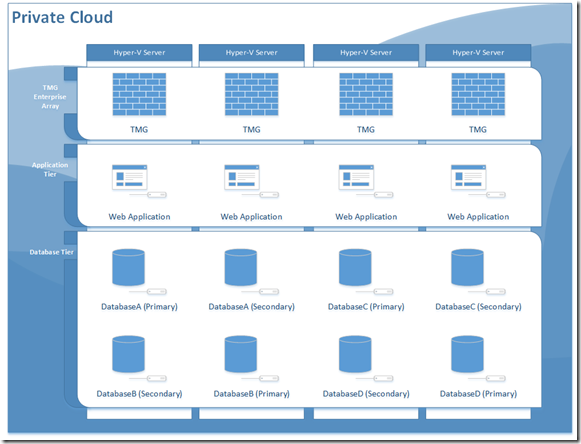
In this scenario I will use 4 identical Microsoft Hyper-V servers each with a LACP LAG tagging all VLANs to the Hyper-V constructing a virtual switch whereby each VM network interface is tagged to a VLAN ID.

Construct a TMG enterprise array placing a virtual TMG server on each Hyper-V host, you will need to provide each TMG a minimum of two network interfaces (LAN & WAN), give each VM 8GB of memory and 4 virtual processors reserving 100% for the CPU reservation. Next configure the TMG enterprise with a unicast NLB on each network interface creating bi-directional affinity. Note: real client traffic (IPs) will need to be able to route to the WAN interface on the TMG enterprise array.

Construct an application tier farm placing a virtual application server on each Hyper-V host, you will need to define the default gateway for each TMG server to be the primary NLB IP address on the LAN interface defined on the TMG enterprise array.

Construct a data tier farm placing a virtual database server on each Hype-V host. I recommend using database mirroring or AlawaysOn availability architecture to obtain application resiliency in favour of clustering, you will need to define the default gateway for each TMG server to be the primary NLB IP address on the LAN interface defined on the TMG enterprise array.

Deploy your IaaS database solution in your data tier farm, for example deploying multiple databases across with mirrors across all of your database servers.

Deploy your SaaS application solution in your application tier farm.

Behaviour

To recap you have deployed a TMG NLB in front of a web farm that uses a database tier backend comprised of multiple SQL servers, but the active database may only exist on one database server.

privatecloud

As you can see an external request is sent to TMG then load balanced out to one of the web application servers which is then routed to a database server. By default traffic is randomly distributed between one or all Hyper-V Hosts.

Problem

How to optimally route requests with affinity in TMG to the Web Application server where the primary database resides so that communication between the application and database don’t transmitting the physical IP network but end up transmitting over the hypervisor network at 10gb with zero latency.

Solution

Configure your web application with application request routing in a workflow to instrument the first request with affinity to sort out the shortest path then set the client origin IP affinity to get routed in the TMG enterprise array to the TMG server that contains the primary database and web farm affinity to send additional requests over time to the web application server that resides on the same server as the primary database.

The result is over time an NLB affinity cache is built where a client request automatically gets routed to the fastest communication path for TMG, web application server and the primary database while reducing traffic on your physical network using Optimal Path Selection (OPS).
How to build a Distributed Service Delivery Network


The internet has inherit problems in its physical connectivity and routing topologies a wide range of issues may occur that impact global availability of a service. Some examples include denial of service attacks that effect a segment of the internet or routing issues within a peer internet service provider. In any case the effect simple a percentage of computers are unable to reach the service destination. It is possible to solve this problem by constructing a DSDN (Distributed Service Delivery Network).

Here is an example for building a Distributed Service Delivery Network where the majority  of the users are in North America using datacenter service providers for both co-location and virtual machines on managed shared infrastructure.

Peering Relationships

When selecting a facility provider it is very important to evaluate the internet peering relationships that exist there the their distance to the core of the internet topology, CAIDA has done research in this area and is a great resource as shown below.

It is worth noting the following Autonomous System (AS) Numbers are dominant networks on the internet and you will want to measure the distance to these networks:

  • AS3356 Level 3 Communications
  • AS6939 Hurricane Electric
  • AS3549 Global Crossing Ltd
  • AS6461 Metromedia Fiber net
  • AS3257 Tinet SpA
  • AS1239 Sprint
  • AS2914 NTT America, Inc
  • AS174 Cogent/PSI
  • AS1299 TeliaNet Global Network
  • AS7018 AT&T Service Inc

The must have connections are AS3356, AS6939, AS174 and AS7018 and I would recommend they be first peer connections. There are multiple ways to measure these relationships such as trace routes or by route view looking glass services, I prefer to use BGPlay.

Two Datacenter Topology

It’s possible to achieve good IP Availability between two datacenters sites the common challenge in any design is ensuring consistent connectivity between datacenters. A dedicated Multiprotocol Label Switching (MPLS) private routing network with packet prioritization will meet this requirement. It is very important to select a single backbone carrier for your MPLS network when possible as such this should also be factored into picking a datacenter provider. You will also need to obtain your own AS Number as well as a single block of IP Addresses.

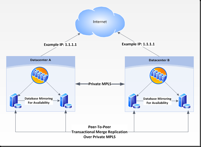
With quality internet peering connections in two datacenters and a private MPLS connection between sites, and AS-Number and IP Block its time to put it all together. In the example shown below you will use your AS-Number to advertise you IP block as a route to both datacenters which means both datacenters will respond to the same IP addresses, this is key. Next you will build identical application server farms that process requests in the same manner with one difference. Each application server farm will use connection strings for database servers that are locally present in each site. The last component is each database server to be configured for peer-to-peer merge replication.

image

As illustrated above each datacenter is advertising the same network and service then over the private MPLS network Peer-to-Peer transactional merge replication is used to keep the databases in each site in sync and then using database mirroring for availability in each datacenter. It is worth noting advertising the same network in both datacenters is not load balancing and you should be prepared in this design for all traffic to be routed to one datacenter. In fact by removing an advertisement to a datacenter you can maintenance the entire datacenter.

Another effect of multiple route advertisements for the public IP block is a symptom similar to geographical location services whereby users would connect to the closest datacenter, in this case they would end up routing to the closest datacenter by way of shortest path on the internet rather then by physical geographical locations.

Multiple Datacenter Topology

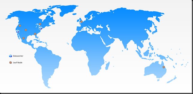
Extending on the two datacenter topology in the multiple datacenter topology add a concept of leaf nodes as shown below.

image

Leaf Nodes which has a similar in physical connectivity to a datacenter only provide have the application service and depend on the private MPLS network for connectivity to either datacenter. While your datacenter may be a private cloud solution your leaf nodes would be a ideal candidate to exist within shared managed virtual infrastructure where you only need to manage your configuration on your virtual machine instances. With leaf node is possible to improve services in broad geographical regions as shown in the example below.

image

Evolving Monitoring for Cloud Network Fabrics


With the rapid global growth in the consumerization of information technology monitoring your application or service has grown increasingly complex. Simply monitoring your solution from one or a few location doesn’t provide effective visibility into the global availability nor does it identify were connectivity issue may be occurring within the internet.

I evaluated options such as services that monitoring your application from multiple locations like AlertSite and solutions that generate statistical analysis like Google Analytics but couldn’t monitor internet fabrics. The real-time web monitor at Akamai was closer but didn’t provide enough granularity. I needed to report & filter my monitoring data by the following data dimensions so I build a ETL data warehouse solution.

  • Date time
  • Client public IP address
  • Number of workstations behind each public IP address
  • Client internet service provider
  • Client location represented as geospatial longitude and latitude
  • Client location represented as City, Region, Country
  • Client public IP reverse DNS lookup
  • Client average response time
  • Correlated relationships between client ISP networks (ARIN)
  • ARIN network identity information
  • A lifecycle that dynamically adds and removes data
  • Identify BGP prefix’s within AS numbers and dynamically generate routing topologies and monitor for changes
  • Collect performance and availability times for all internet fabric paths and dynamically represent that data
  • Collect real internet fabric network topologies by identifying actual routes that packets flow
  • Granularity to the point that a single client internet connection can be identified and analyzed all the way back to the service endpoint.
  • Broad reporting to alert and identify broad issue with peering relationships, and the internet in general.

Here is screenshot of what the beta of this technology looks like, the example below is clients connecting to services at iQmetrix.

clip_image002